
Symbols are an important aspect of engineering communication. They are short, potent, and international in communicating meaning without words. The First Angle Projection Symbol is one of the best-known symbols of technical and mechanical drawing, a small but vital graphic telling engineers, designers, and manufacturers how an object in 3D is projected in 2D.
The symbol is not merely a drawing. It is a call for order, standardization, and clarity in technical drafting. The symbol appears on blueprints, CAD drawings, and architectural blueprints, where it tells the professionals what projection method is employed in the specific drawing, a consideration that will decide how the parts are envisioned and built.
What Is the First Angle Projection Symbol
The First Angle Projection Symbol is a small geometric symbol that graphically shows how an object is projected onto the two planes. It tells the reader about the relationship of views of the object (front, top, side).
In first angle projection, the object is in front of the projector and in front of the plane of projection. The views are therefore on the opposite side of where they really stay in actuality.
For example:
- The right side view is on the left side of the front view.
- The top view is placed below the front view.
First Angle Projection Symbol is a handy way of indicating that the drawing is drawn to this particular technique so that it is not confused with Third Angle Projection, widely used in North America.
Appearance of the First Angle Projection Symbol
First Angle Projection Symbol can be easily recognized and stands out as different from other forms.
It consists of two different shapes:
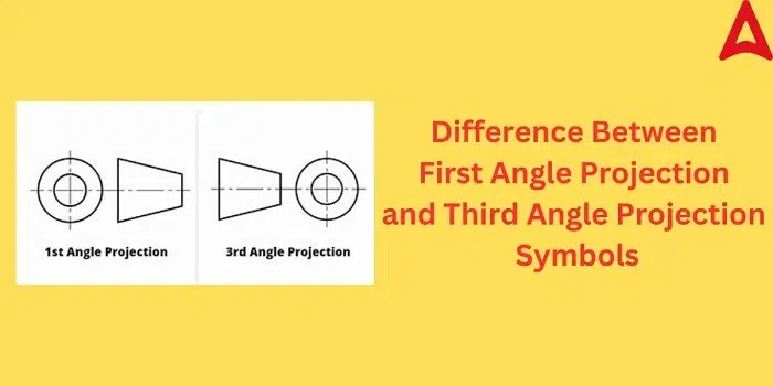
- A truncated cone illustrating the side view of an object.
- A circle, the front view of the same thing.
The circle is to the left of the truncated cone in the First Angle Projection Symbol. The reader’s immediate cue by this positioning is that the projection is first angle.
| Component of Symbol | Representation | Meaning |
| Left circle | Front view of the cone | Represents what the object looks like if looked at head-on |
| Right cone | Side view of the same object | Projected orientation indicated |
| Arrangement | Cone on right, circle on left | Shows first angle projection |
This is the opposite of the Symbol for Third Angle Projection, with the circle on the right.
Historical Background of the First Angle Projection System
The projection system theory was developed from descriptive geometry, which French mathematician Gaspard Monge created in the 18th century. His methods allowed engineers to mathematically project three-dimensional objects onto two-dimensional surfaces.
Two of them already existed in the 19th century: First Angle and Third Angle.
The First Angle Projection System was used worldwide across Europe and Asia and was utilized most widely by countries following the ISO standards.
Third Angle Projection System was the standard in the United States of America, Canada, and the UK as per ANSI standards.
Where they were used together, standardizing agencies provided symbols to indicate which system was adopted. The First Angle Projection Symbol was adopted by ISO 5456-2 as the global standard.
Understanding the Principle of First Angle Projection
In the first-angle projection system, the projection plane is located behind the object. The object covers the line of sight between the observer and the projection plane, and the image is therefore projected on the opposite side.
This can be stated as:
- The observer is observing the object.
- The object covers the line of sight between the observer and the projection plane.
- The shadow is thrown on the opposite side of the object.
| View | Position on Drawing |
| Top View | Below the Front View |
| Bottom View | Above the Front View |
| Right Side View | Left of Front View |
| Left Side View | Right of Front View |
Although this arrangement perplexes the students, it is well-organized and systematic and can be easily read by professionals.
Difference Between First Angle and Third Angle Projection
In order to better understand the importance of the symbol, it is helpful to compare in what way the symbol differs from the third angle method of projection.
| Feature | First Angle Projection | Third Angle Projection |
| Position of Object | Between observer and projection plane | Between projection plane and observer |
| Right Side View | Drawn on left side | Drawn on right side |
| Top View | Drawn below front view | Drawn above front view |
| Circle in Symbol | Placed on left of cone | Placed on right of cone |
| Standard | ISO (Europe, Asia) | ANSI (USA, Canada) |
The two systems are opposites in layout, and it is therefore extremely crucial to use the correct symbol on drawings.
The Role of the First Angle Projection Symbol
The main role of the First Angle Projection Symbol is consistency and legibility. Engineering drawings are used globally by teams that may not share a language, and visual communication therefore has to be unambiguous.
The symbol helps to:
- Avoid misunderstandings.
- Ensure adherence to standards.
- Avoid manufacturing mistakes.
- Facilitate communication.
Without the symbol, designers may receive the view arrangement wrongly and cause costly manufacturing or assembly mistakes.
Symbol Position in Technical Drawings
The First Angle Projection Symbol is typically placed on the title block or bottom right of a technical drawing. This reveals the system of projections to the viewer at once.
Alternative placements are:
- Near the drawing scale or revision table.
- On CAD templates or drawing sheets for standardization.
On AutoCAD, SolidWorks, and CATIA, it is automatically located in the template by default.
Placement of the First Angle Projection Symbol in Reports
Students and engineers may be told to put the symbol on reports or term papers. This is how to do it:
| Method | Steps |
| Insert Image | Download symbol image and insert by selecting Insert → Picture → From File |
| Use CAD Library | Select “First Angle Projection Symbol” from AutoCAD or SolidWorks internal symbols |
| Manual Drawing | Freehand draw truncated cone and circle and place circle on the left |
| Word or PowerPoint | Insert → Shapes → Freehand draw combined cone and circle |
| Unicode Alternative | Not available; image or custom vector needs to be inserted |
If correctly used, the symbol adds professionalism and readability to reports or presentations.
Industrial and Educational Uses

The First Angle Projection Symbol finds use in nearly every technical education and industrial field.
In education:
- It is used by engineering students of mechanical or civil engineering for the practice drawing of orthographics.
- It helps learners project 3D objects onto 2D planes.
In industries:
- It is used in machine component manufacturing drawings.
- It is used in industrial design drawings and in architectural drawings.
- It is used in assembly manuals and product manuals.
The First Angle Projection Symbol is utilized by Germany, Japan, India, and France for technical drawings of ISO standard.
Also Read: National Symbol of India: Meaning, Importance and Cultural Identity
Role of Projection Symbols in Engineering
First angle and third angle projection symbols are essential to prevent misunderstanding. In their absence, even experienced engineers misunderstand the orientation of an object.
They provide:
- Universal consistency in production operations.
- Language-independent visual directions.
- Technical standardization required for documentation and certification.
A minute misunderstanding in precision-critical industries results in heavy losses. One uncomplicated simple symbol is enough to make all people dealing with the drawing understand it properly.
The Psychology of Symbol Recognition
The mind of man is programmed to perceive patterns faster than letters. The First Angle Projection Symbol, although simple, is a figure that tells an engineer at once how the drawing is to be interpreted.
Its clear use of geometric figures, a cone and a circle is typical. The moment engineers see the circle on the left, their mind immediately recognizes it as first angle projection mode. Immediate recognition prevents errors of interpretation and is helpful in visual literacy.
Standardization and Regulatory Bodies
There are two bodies that are at the forefront of regulation of use of projection symbols in engineering:
- ISO (International Organization for Standardization) – Applies First Angle Projection by default.
- ANSI (American National Standards Institute) – Third Angle Projection is the preferred standard.
Both methods can be applied but need to be indicated. The First Angle Projection Symbol is ISO 5456 and other standard compliant drafting.
Why the First Angle Projection Is Still Popular
First Angle Projection system still reigns supreme in Europe and Asia due to traditional draft training and sense of reasonableness in design.
Benefits:
- Graphically represents true-world observation.
- Simple to acquire for students once understood.
- Meets international ISO standard.
- Industrial manufacturing process standard.
This system still makes up the foundation of technical drawing teaching and world production communication.
The First Angle Projection Symbol is arguably the smallest, but most significant symbol in the history of engineering. It is not just a technique for visualization, but a whole way of thinking in terms of simplicity, consistency, and universality.
Since descriptive geometry’s early development a few centuries ago to its application in CAD programs in the present era, the symbol serves to allow technical drawings to be readable by engineers on other continents. It’s an international precision symbol that unites generations of designers and producers.
Each time an engineer looks at that tiny cone-and-circle symbol with the circle on the left, they’re reminded to keep in mind that the greatest simplicity is the greatest clarity in even the most simple symbols. It’s a reminder of how geometry, logic, and design can be applied in a manner to build a language which is comprehensible to everyone.