
Transformers are largely utilized in electrical engineering to measure and control current in a safe way. Among these, the current transformer (CT) is one of the most widely used transformers. It helps to measure large currents by converting them into smaller, safer currents which can be measured using meters or relays.
In schematic diagrams, all the elements are represented. The current transformer symbol is one of the simple but effective electrical symbols which tell engineers how the current flows through the system.
What Is a Current Transformer (CT)
Current transformer is a type of instrument transformer used to measure or monitor alternating current (AC). It reduces high levels of current to low, proportionate levels so that ordinary measuring devices like ammeters or protection relays are able to measure them safely.
| Feature | Description |
| Full Form | Current Transformer (CT) |
| Purpose | Measurement of large AC current safely |
| Type | Instrument transformer |
| Output | Scaled-down current (proportionate to input) |
| Common Ratio | 1000:5, 500:5, 100:5 |
For example, a CT with a ratio of 100:5 will convert a current of 100 amperes into 5 amperes, which is safe for measurement.
Current Transformer Symbol in Circuit Diagrams
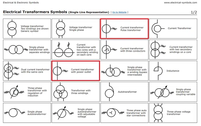
The symbol for the current transformer is simple to recognize and easy to spot in an electrical circuit. It would usually consist of two windings, one as the primary winding and one as the secondary winding, usually symbolized with a circular or core loop surrounding them.
| Symbol Part | Meaning |
| Primary Winding | Carries main current from power line |
| Secondary Winding | Delivers small, measurable current |
| Magnetic Core | Indicates electromagnetic link between windings |
| Terminal Mark (P1, P2, S1, S2) | Expresses direction and polarity |
In most circuit diagrams, the symbol looks like two loops with a circular core between them, sometimes drawn as concentric circles or a rectangle and lines of connection.
Visual Description of CT Symbol
The current transformer symbol is represented by a circle in which two lines pass through it — one for the primary coil and the other for the secondary.
It may be described as:
- Primary winding: series connected with the main power line.
- Secondary winding: tapped to metering, relay, or protection circuit.
This ring-shaped configuration represents the iron core that magnetically couples both coils.
Principle of Operation of a Current Transformer
The current transformer works on the principle of electromagnetic induction.
When in the primary winding, the alternating current induces a magnetic field in the core. The external magnetic field produces an induced current in the secondary winding equal to the primary current but smaller in amplitude by a large amount.
Step-by-step operation process:
- High current passes through the primary conductor.
- The magnetic field is induced in the CT core.
- Induced voltage is produced in the secondary winding.
- Secondary current is fed to the measuring instrument.
- The meter indicates current in a diminished proportion.
It allows measurement of high currents with safety without direct connection to high-voltage cables.
Easy Formula Applied in Current Transformer
Relationship between the primary and secondary currents is given by:
Ip / Is = Np / Ns
Where:
- Ip = Primary current
- Is = Secondary current
- Np = Turns in the primary winding
- Ns = Turns in the secondary winding
For example, if a CT has 100 turns on the secondary and 1 turn on the primary, then the current gets attenuated by 100 times.
Types of Current Transformers
There are several types of CT depending upon application and construction.
| Type | Description |
| Wound Type | Primary and secondary windings wound over a core. Used for accurate measurement. |
| Bar Type | The primary is a single bar conductor over the core. Common in power systems. |
| Toroidal Type | Does not have a primary winding; the line cable itself passes through the ring-shaped core. |
| Summation Type | Reduces a number of currents from different feeders to one output. |
Both employ the same basic symbol but can be distinguished with slight variations to denote its design type.
Purpose and Application of Current Transformer
The CT has two main purposes, measurement and protection.
Measurement:
- Used with ammeters and wattmeters to measure current flow in high-voltage systems.
- Helps convert high current to lower values like 5A or 1A for safe measurement.
Protection:
- Used in conjunction with protective relays to detect overcurrent or faults.
- Disconnects circuits under faulty conditions.
Monitoring:
- Used in power distribution panels, energy meters, and load management systems.
Applications of Current Transformer
Current transformers are used in the majority of electrical and industrial applications.
| Application | Example |
| Power Stations | To measure generator output |
| Substations | For current monitoring and relay operation |
| Industrial Plants | For load management and protection |
| Energy Meters | For billing and current measurement |
| Transmission Lines | For measurement of current flow |
They are essential to safety and efficiency in electrical circuits.
Advantages of Current Transformer
- Provides safe measurement of high current.
- Enables standard meters to be utilized for high currents.
- Electrically isolates measurement devices from high voltage.
- Enhances accuracy and safety for power measurements.
- Reduces utilization of high-current-rated equipment.
Safety Precautions Using CTs
Although CTs provide safe measurement of current, some precautions must be adopted.
- Never open the secondary winding with the condition of energized primary.
- Connect in proper polarity (P1, P2, S1, S2).
- Ground the secondary side at all times to avoid voltage buildup.
- Never short the secondary winding except during test.
- Use proper burden (resistance) for accuracy.
These procedures insulate both the CT and operator from hazard.
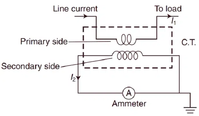
Current Transformer Symbol in Schematics
In schematics, the CT symbol helps identify measurement or protection points.
A basic CT circuit can comprise:
- Power line going through the CT primary.
- Secondary wired to an ammeter or relay.
- Ground terminal for protection.
Sample depiction in diagrams:
- A circular shape with two lines connecting it.
- Labeled as “CT” or “Current Transformer.”
- Often depicted close to meters, relays, or switchgear.
Also Read: Swastik Symbol for Home: Meaning, Usage, and Significance in Hindu Culture
Difference Between Current Transformer and Potential Transformer
| Characteristic | Current Transformer (CT) | Potential Transformer (PT) |
| Role | Measures current | Measures voltage |
| Connection | Connected in series | Connected in parallel |
| Output | Low current (1A or 5A) | Low voltage (110V) |
| Symbol | Two circular core coils | Two parallel line coils |
| Application | For relays and ammeters | For voltmeters |
CTs are employed in measuring high current while PTs are employed in the measurement of voltage. Both play important roles in power systems.
Commonly Used CT Ratios
| Primary Current | Secondary Current | Ratio |
| 100A | 5A | 20:1 |
| 200A | 5A | 40:1 |
| 500A | 5A | 100:1 |
| 1000A | 5A | 200:1 |
The ratio is utilized in determining the actual current from the meter reading.
Troubleshooting Common CT Problems
- Incorrect Readings: Resulting due to incorrect ratio or reverse polarity.
- Open Circuit in Secondary: Hazards; can generate high voltage.
- Overheating: Due to high burden on the secondary circuit.
- Magnetized Core: Decreases accuracy; demagnetization can be required.
Periodic testing and calibration provide for dependable performance.
Significance of the Current Transformer Symbol
The CT symbol in electrical plans assists engineers in:
- Quick identification of current measuring points.
- Accurate planning of protective circuits.
- Safety during maintenance.
- Grasping system flow in control panels.
Reading advanced circuit diagrams would be extremely challenging without standardized symbols.
The current transformer symbol depicts one of the most important components used in electrical measurement and protection schemes. The symbol shows the way the high current is passed safely to relays and meters.
A CT not only helps in the measurement of the current but also guards the electrical system against faults and overloads. In power plants, factories, and substations, the simple CT symbol on schematics is a sign of immense importance, safety, precision, and control.
Understanding this small yet crucial symbol helps engineers, students, and technicians confidently and clearly design and maintain electrical systems.